SD-WAN Market
In recent years, the SD-WAN market has witnessed the emergence of various vendors, including Fortinet, SilverPeak, Versa, Palo Alto, VeloCloud, Meraki, Cisco SD-WAN (formerly Viptela), and Juniper, among others. While these vendors share a common goal, each distinguishes itself with unique features. For instance, VeloCloud stands out by offering per-packet load balancing, the ability to optimize the underlay within the overlay using Forward Error Correction (FEC), and a proprietary protocol for tunnel establishment and real-time traffic monitoring. Viptela, now part of Cisco, presents a feature-rich platform leveraging its proprietary Overlay Management Protocol (OMP) for routing, albeit at a higher cost. Meraki excels in user-friendliness, particularly in VPN setups, requiring minimal configuration for a robust network.
SD-WAN Market – Trade-Offs:
Despite their differences, all SD-WAN solutions utilize a central controller for configuration management and rely on IPSec tunnels for inter-location traffic. While IPSec ensures secure communication, it introduces a trade-off in Maximum Segment Size (MSS). In IPSec tunnels with up-to-date algorithms, the largest MSS is approximately 1360 bytes, leading to a 7% loss in total data utilization per packet. Although seemingly insignificant per packet, this loss accumulates over time.
History of Juniper SD-WAN:
Understanding Juniper SD-WAN requires delving into its origins. Initially developed by 128T, Juniper SD-WAN aimed to revolutionize how SD-WAN devices interacted with networks. Traditional networks prioritize fast packet forwarding based on destination IP addresses, resulting in asymmetrical traffic flow. Recognizing the growing importance of security, 128T sought to create a network that was fast, reliable, scalable, and secure, aligning with the principles of zero-trust.
Brief Overview:
128T redefined the traditional router approach by directing traffic based on destination service rather than IP addresses. Incorporating zero-trust principles, they mandated that all users must have explicit permission to access any configured services. 128T maintains extensive network state information, tracking every unique packet based on characteristics such as source and destination ports, source and destination IPs, source tenant, and destination service.
To address the IPSec trade-off, 128T introduced a proprietary protocol named Secure Vector Routing, operating over Peer Paths tunnels. This approach allows the utilization of the full Maximum Transmission Unit (MTU) for packets, eliminating the MSS-related data loss issue. The use of Network Address Translation (NAT) further conceals source and destination IPs on the network, ensuring encrypted payload transmission without introducing overhead in TCP/UDP streams.
SVR Overview:
As Packet Pushers wrote, SVR is as much an ideology as it is a protocol. SVR is how 128T can have “tunneless” tunnels, route traffic-based destination application rather than IP addresses, and segment that traffic based on groups of users. SVR stands for Secure Vector Routing, and it is the technology to handle what 128T saw as deficiencies within the SD-WAN ecosystem. This technology allows for there to be little to no loss on the MSS of a packet (minus the first packet within a flow), keep traffic secure, and to allow routing based on applications to be more human readable. SVR can be used between SVR peers or is used through standard routing procedures. While it can do standard routing, SVR really shines when coupled with multiple Session Smart Router peers.
SVR – Waypoints:
SSRs route to peers using Waypoints. Waypoints are the IP reachable interfaces that are configured on the routers. Waypoints can be behind NAT, static IPs, or received by DHCP. The only requirement for a waypoint is that it is reachable via IP (IPv4 or IPv6). When traffic is sent through an SSR, it checks if the next-hop for that destination service is another SSR. If it is, then SVR operation occurs; however, if the destination service is not reachable through another SSR, it is routed via traditional routing. Due to SSRs interfaces being IP reachable, it is possible that a destination service is reachable through multiple SSRs. Each receiving SVR router will look at the destination service and determine if it needs to be sent via SVR or if it is going out a traditional routed interface.
SVR – Peer Paths:
SSRs determine which waypoints they have access to by their adjacencies. If two routers are adjacent to each other, they can advertise and route directly to each other with SVR. These adjacencies create those “tunneless” tunnels which are called Peer Paths. Traffic sent via SVR runs over these Peer Paths to each receiving SSR. Peer Paths run BFD packets using port UDP port 1280 which record the loss, latency, and jitter of the path. By default, these BFD packets run once every 1 with a hold time of 3 seconds. There can be multiple peer paths between the same waypoints that have different BFD timers. This is commonly used for SSRs that have a wired and wireless circuit. While traffic from the SSR spoke is going to the same destination waypoint at the hub, a different Peer Path is used for the wireless circuit where BFD timers are set at a much higher rate to limit the wireless usage. This timer is recommended to be set to one BFD packet sent every 60 seconds with a hold time of 180 seconds.
SVR – Neighborhoods:
Neighborhoods are used to create the adjacencies and peer paths between SSRs. SSRs are said to be adjacent if they are in the same neighborhood. There are three neighborhood modes: spoke, hub, and mesh. Each SSR must have compatible modes before the adjacencies and peer paths can be created. Below is a graph that determines what settings have the routers establish adjacencies.
Will Adjacency Form?
| Neighborhood Modes | Spoke | Hub | Mesh |
| Spoke | No | Yes | Yes |
| Hub | Yes | No | Yes |
| Mesh | Yes | Yes | Yes |
SVR – Network State Overview:
Session Smart Routers track network state and are session oriented. A session is built from two flows, forward flow and reverse flow, and every session that has a unique 5-tuple packet header is attached into its own session. This 5-tuple header includes the source/destination IP, source/destination Port, and the protocol that is being used. If the destination service is at an adjacent SSR though SVR, just the payload is encrypted with the IP/Ports being changed. This is done so man-in-the-middle attacks can’t be performed and that if the traffic ends in the wrong hands, the data cannot be decrypted with the real source and destination IPs hidden. This NAT and encryption of the payload has multiple advantages for network performance.
Network State – NAT:
NATing is an integral part of how SVR functions. SSRs will take SVR traffic that flows over the peer path and NATs that traffic to one of it’s waypoint addresses. When it performs this NAT, it removes the private TCP/IP headers and replaces that header with its own. It can even take traffic that is TCP, like web traffic, and when it NATs the traffic, it will change it from TCP to UDP. The NAT it performs is like how a traditional router NATs. It has a NAT table, and every session uses a unique source port which allows it to have up to 65535 unique sessions per waypoint IP.
Let’s look at the following diagram for an example of this.

Here are two SSRs that are connected though the 1.1.1.0/24 network. R1 is using 1.1.1.1 and R2 is using 1.1.1.2. Each SSR has a private LAN with a device on 10.0.0.2 and 192.168.10.2 respectively. Traffic sent between the SSRs is going to use SVR as they have an adjacency. If 10.0.0.2 sends an ICMP packet to 192.168.10.2, the packet will go to R1 to be processed.
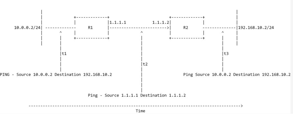
In this diagram, the packet will hit R1 at time t1, where R1 will look in its routing table and see the destination address is at an adjacent SSR. R1 will send the traffic to R2 and will update the IP headers at time t2. The source address of the packet will be R1s source waypoint, and the destination address is R2s waypoint address. When R2 receives the SVR’d traffic, it will de-encapsulate the data and see the real destination address is 192.168.10.2 and forward the traffic through traditional routing.
As this was ICMP, the IP type wasn’t changed, but let’s see an example where a webserver is being used.
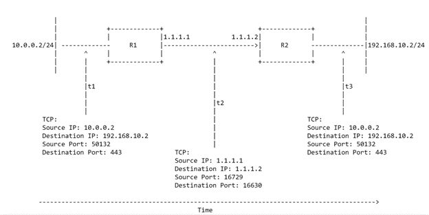
This is the same diagram above except 10.0.0.2 is sending traffic to a web server that is at R2 – 192.168.10.2. Like before, traffic is going to be sent from 10.0.0.2 to R1, where R1 will look at its routing table and see the traffic is destined to a network that is being advertised by R2. The traffic is then going to go over SVR and be NAT’d to R1s waypoint address. In this example, you can see the headers were changed from the private IPs and ports to ports that are on the SSR. The source address of the packet will be R1s source waypoint, and the destination address is R2s waypoint address. When R2 receives the SVR’d traffic, it will de-encapsulate the data and see the real destination address is 192.168.10.2 on port 443 and forward the traffic through traditional routing.
Outside of security, there are other advantages to having SVR traffic NAT’d to waypoint addresses. NATing the traffic to an IP on the router and changing of the Ports to unique numbers allow the traffic to not get load-balanced by any middle boxes. Many networking devices will load-balance traffic based on a hashing algorithm that can look at the hash of the whole frame, hash of just the IP headers and/or hash of the TCP/UDP headers. This can cause issues known as elephant flow which is common with traditional IPSec tunnels since as all traffic sent over the tunnel has the same 5-tuple header (the IPSec header. With SVR, every flow has a unique 5-tuple, and the traffic will be better load-balanced along the path, minimizing Elephant flows from occurring. Secondly, this helps minimize issues with middle-ware boxes, such as modems and firewalls, from blocking traffic. Traffic that is sent between two SVR routers can NAT the traffic that was TCP to be sent over the Peer Path as UDP. If any router in the middle worries about network, The NAT’d UDP traffic will then be able to bypass any middle box that cares about state since it is very hard to know the network state of UDP.
Network State – Waypoints:
If the two SSRs are changing the IPs and ports for the traffic that is being sent, each receiving SSR needs to know the real header information of each packet. This is done using a network cookie, called Metadata. Metadata is information that is inserted into the payload of the first packet of every new flow that is sent to an SVR peer. This Metadata contains the internal source/destination IPs, ports, waypoints, application name, and tenant names. This data is encrypted and put into the payload of the packet to ensure that middle boxes do not mess with that cookie. It is important that the Metadata is always received between each SVR peer. All subsequent packets that match the NAT’d 5-tuple are then associated with that session, and the receiving SSR will change the header information of each packet to what was in that session’s Metadata. The Metadata does minimize the number of bytes that is in the payload, but the Metadata is only sent first the first packet of every flow that uses SVR. All subsequent packets are sent without it since the adjacent router already has the mapping.
Lets expound upon the above diagram more.
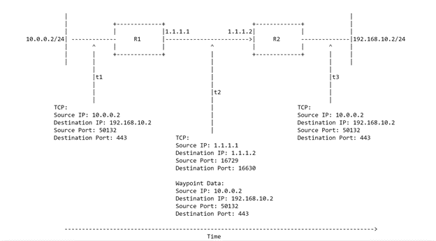
10.0.0.2 is sending traffic through SVR to a webserver hosted at 192.168.10.2. When the traffic hits R1 and R1 does its route lookup, it is going to forward the traffic to R2 through SVR. On the first packet of this session, R1 will insert the Metadata into the payload of the packet. When R2 receives this Metadata, it is going to know that any traffic from 1.1.1.1 to 1.1.1.2 with a source port of 16729, and a destination port of 16630 is all part of the same flow. The metadata contains the private source/destination IPs and ports to let R2 know how to translate the subsequent packets. At time t3, R2 takes the packet and changes the headers to match what was in the Metadata packet. Every packet in this flow will be translated the same way for the lifetime of that flow.
Network State – Securing Traffic:
SVR encrypts its data in two different ways. First, every packet that is routed via SVR has its payload encrypted though the use of public/private keys using well established security protocols such as aes-256. Only the payload is encrypted, unlike traditional IPSec tunnels. This encryption will use private/public keys and HMAC can be used on top of the keys to authenticate every packet, though the router will take a performance hit.
BFD packets that run over the Peer Path are used to exchange the Peer keys that are used for the payload encryption. The keys have a lifetime and when the lifetime is nearing an end, SSRs will use BFD to exchange the new keys. The second way it secures traffic is using encryption of Metadata though PSKs and using HMAC to authenticate all Metadata packets. As Metadata is used on only the first packet of every SVR flow, the SSR will not take a performance hit.
SSRs use adaptive encryption on the payloads to increase performance while maintaining its security posture. When traffic is being sent over SVR, the SSR will inspect the type of traffic that is being sent. If the traffic is already encrypted, such as SSL, the SSR will not encrypt it. If there is a lot of web traffic being sent, this allows for more packets to be sent/received by the SSRs as they won’t have to do a per packet encryption on the payload.
SVR Routing – Overview:
128T wanted to change how IT people viewed the network when they made SSR software. They viewed the network, not in a list of connected subnets, but as a service that is provided to the end-user. End users do not care about what IP a service or application uses, but about the service itself. 128T decided to not use traditional routing, but instead utilize the service view end-users have.
SVR Routing – Services:
Traditional routers forward traffic based on the destination IP address. The routers hold network state in the form of routing protocols, NAT, and/or ACLs, but don’t care about the importance of the application without some form of QoS. Traffic is queued as first-in-first-out (FIFO) which can cause traffic to be dropped during moments of congestion. 128T service model has the routers understand services in a way traditional routers cannot. 128T utilizes a construct called a service that is a list of IPs, ports, domains, and urls. Like traditional routing, the more specific service wins in the route table. Each service can utilize a different service-policy that stipulates the traffic priority, which egress circuit is preferred for this service (broadband vs mpls vs dia), and how to handle the traffic manipulation during times of failure.
The idea is to have individual applications, or groups of similar applications grouped into their own services. These services can have varying service-policies so that the routers will forward traffic based on the intent of the administrator. Here is an example of what a simple service can look like.
name Internet-OutBound
security internal
address 0.0.0.0/0
generate-categories true
access-policy Spoke
source Spoke
exit
service-policy Internet-Access-Backup
share-service-routes false
In this example, the service is called “Internet-OutBound” is contains a default route. This service would be applied at each SSR with the next hop being the connected ISPs. A more common service would look like this.
name ITSNetwork
enabled true
scope private
security internal
tap-multiplexing false
transport tcp
protocol tcp
exit
transport udp
protocol udp
exit
transport icmp
protocol icmp
exit
address 172.16.3.0/24
application-identification inherited
generate-categories false
This service is a network that is being advertised to all adjacent SSRs and it is announcing the prefix 172.16.3.0/24 for all TCP/UDP/ICMP traffic.
SVR Routing – Tenants:
128T also uses a construct called Tenancy that allows users to reach certain services. These tenants are tags that are applied for groups of users to segment traffic. Services deny all tenants unless they are explicitly allowed to reach that service. This is the zero-trust model that was stated earlier, and each flow that goes through an SSR has a tenancy check against the service that they are trying to reach. If the tenant is allowed, then the traffic is forwarded. If the traffic is denied, then the SSR will drop the traffic. Tenancy can be provided in two ways: either each network-interface/vlan has a tenant associated to it, or tenancy is provided by pre-defining IP addresses. If tenancy is associated to an interface, then all traffic that goes over that interface has a tenancy tag that is applied to each flow. This tag is only added once, and it is added at the first interface that the traffic hits. If traffic is going through multiple SSRs, each with different tenant tags, then the tag is only applied at the first interface, and traffic rules are applied accordingly.
Tenancy by IP address is more flexible but requires more configuration. This method allows for induvial IPs, or blocks of IPs to be configured under a tenant. The SSR that the traffic hits first will look up the source IP and compare it against its tenancy table. When it finds a matching address for a tenant, that tenancy tag is applied to the flow and service rules are checked.
Example of tenancy by address is below:
tenant-prefixes datacenter-network
tenant datacenter-network
source-address 10.0.0.0/24
exit
SVR Routing – Services with Tenants:
Below shows how services and tenants work together. In the ITS service that was used earlier, it shows the 172.16.3.0/24 network with TCP/UDP/ICMP protocols specified in the service. This now has all the tenants that are allowed to reach this service.
name ITSNetwork
enabled true
scope private
security internal
tap-multiplexing false
transport tcp
protocol tcp
exit
transport udp
protocol udp
exit
transport icmp
protocol icmp
exit
address 172.16.3.0/24
application-identification inherited
generate-categories false
access-policy datacenter-network
idp-policy none
source datacenter-network
permission allow
exit
access-policy ASA-Transit
idp-policy none
source ASA-Transit
permission allow
exit
access-policy SynderoNetwork
idp-policy none
source SynderoNetwork
permission allow
exit
access-policy HQ-Voice-Network
idp-policy none
source HQ-Voice-Network
permission allow
exit
access-policy site-data
idp-policy none
source site-data
permission allow
This service shows that there are five tenants allowed to use it: datacenter-network, ASA-Transit, SynderoNetwork, HQ-Voice-Network, and site-data. All other tenants will be denied reaching this service that aren’t specifically listed in the service. Below is a list of the SSRs route table.
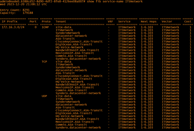
The router shows that all those tenants are allowed to reach the ITS network. If a particular tenant is not allowed to reach the service, the next hop would be blank.
SVR Routing – Putting it Together:
Basic of SVR have been explained during this document with it showing how individual pieces work. This section is going to put it all together and show what happens when PCA and PCB attempt to connect to ServerA via https. Diagram 3.1 shows the network setup.
Diagram 3.1
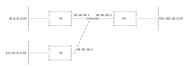
In the diagram, there are three SSRs that all have adjacencies; R1, R2, and R3. R1 has the network 10.0.0.0/24 with PC A on 10.0.0.2. R2 has the network of 172.16.0.0/24 with PC B on 172.16.0.2, while R3 has the 192.168.10.0/24 network with a server with the IP of 192.168.10.2. Let’s do a packet walk when PC A attempts to connect to 192.168.10.2.
Diagram 3.2
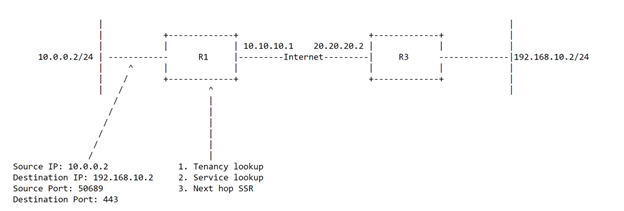
PC A initiates the traffic to the server and the traffic hits the SSR. The SSR does a tenancy lookup to apply a tenant to the flow. SSR looks up its tenancy table and sees the following information.
tenant-prefixes: R1-data-network
tenant: R1-data-network
source-address: 10.0.0.0/24
The SSR then does a service lookup to see which service has the longest prefix-match to get to the destination address. It does a lookup on its table and finds the following service:
name R3-HTTS-Server
enabled true
scope private
security internal
tap-multiplexing false
address 192.168.10.0/24
application-identification inherited
generate-categories false
access-policy R1-data-network
idp-policy none
source R1-data-network
permission allow
exit
access-policy R2-data-network
idp-policy none
source R2-data-network
permission deny
exit
It sees that the R1-Data-network is allowed to reach the server, so the traffic is allowed to proceed. R1 sees the destination address is R3 that it has an adjacency to, and it starts the SVR process.
Diagram 3.3
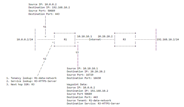
R1 will encrypt the payload and add the waypoint cookie into the first packet that is sent across. This waypoint cookie will have the true source/destination IPs and source/destination Protocol. This metadata will also include the source Tenant and the service it is trying to reach. R1 will NAT the headers and change the ports of the original packet to free ports it has in its NAT table. Diagram 3.3 showcases this.
R2 will receive the SVR’d traffic and decrypt the metadata. When it decrypts the data, it will do a lookup in its route table to see if the tenant R1-data-network is allowed to reach the R3-HTTPS-Server. It will then do a lookup to see where the R3-HTTPS-Server is and see what the next hop is. In this instance, the next hop is R3s LAN interface, and the traffic headers are changed to the header information in the metadata and forwarded.
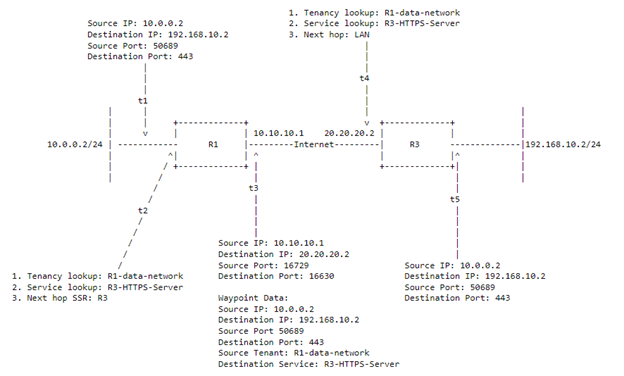
To recap, there are 5 steps shown in the diagram that the SSRs are taking. First, the router receives the packet and does service/tenant lookup to see what is the longest prefix match service that tenant is allowed to reach. Once it has selected the destination service, it will send the traffic through SVR. SVR encrypts the data in the payload and inserts the metadata information into the first packet it sends. The visible TCP/IP headers are NAT’d to the sender SSRs waypoint address and sent to its adjacent SSR. The receiving SSR will decrypt the packet and look at the metadata and do another route/tenant lookup. It will confirm that the tenant is allowed to reach that service and see what the next hop is for the service mentioned in the metadata. Once it finds the next hop, it will change the headers back to what is in the metadata and forward the traffic. All subsequent traffic that has the SVR headers (the header at t3) will be NAT’d the same way on ingress.